Two steps forward, one (exploding) step back. October 25, 2009
In the past couple of weeks, I managed to do a little more work on the soda machine hack. With the hardware to interface 110VAC relays to 5VDC logic done, the next step is to create a means of connecting it to the TINI390 board. This has turned out to be a little more complex than I’d anticipated, specifically because I don’t have direct access to the various I/O pins (at least not through its Java VM). The TINI is set up more like a microprocessor than a microcontroller; all the I/O is done by reading from and writing to specific memory locations, divided into several pages. The board has only eight general-purpose I/O pins, but it has a twenty-bit address bus and five usable “Chip Enable” pins. All communication with the on-board peripherals (such as the flash memory and probably the Ethernet) is carried over the same data pins, so anything I attach needs some capability to decode addresses in order to avoid reading or stomping on unrelated stuff.
Since there’s only a limited amount of stuff I need to connect to the TINI, I went with a moderately simple solution: I ignore the actual address pins and pay attention only to the Chip Enables. For example, accessing any memory location in the range 0x800000 to 0x8FFFFFF activates Peripheral Chip Enable 0 (PCE0); since I only need eight bits, I can write anywhere in that range and watch only the enable pin, ignoring the address completely. While this effectively wastes 16,777,207 possible bits, it greatly reducing the complexity of the electronics.
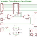
With everything needing to access the same set of pins, however, the board layout started to get a bit hairy. I’m planning to build the system as a set of stacking modules, each with a specific function. This way, I can build the thing piecemeal and add features as I go. The first module is for reading the soda selection. It is fairly simple: when a soda is selected, one of the seven input pins goes ‘high’ for about a quarter of a second. An eight-input OR gate triggers the clock of a flip-flop which grabs and keeps the input. The TINI can then read the selection at its leisure. The DRST (external device reset) pin also triggers the flip-flop’s clock; with no input from the selection detector, this effectively clears the flip-flop. A standard two-input OR is all that’s needed to handle the address decoding.
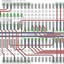
The soda selection encoder has been built on a breadboard and undergone some testing on the benchtop; it seems to work perfectly. In attempting to test it with the actual selection detector connected to the soda machine, however, I experienced a minor disaster. Apparently, I attached the interface board’s AC neutral to the soda machine’s AC ‘hot’ — I’m attaching this to the lighting circuit, the wires of which are all the same color. When I pressed a soda button, all of the inputs were powered simultaneously, drawing much more current than expected. All of the board’s indicator LEDs lit at the same time with alarming brightness, followed by an alarming darkness. One of the LEDs was actually slightly blackened after the experience; it is just luck that it didn’t actually explode. I suppose either the external LED or the diode inside the optocoupler blew first, then the reverse current killed the surviving diode. Luckily, after some tests, it looks like only that LED/optocoupler pair was destroyed. It should be moderately easy to replace.
Leave a Reply
You must be logged in to post a comment.